
Logica secuencial VHDL
Objetivos
- Poder desarrollar circuitos digitales usando la herramienta de Edición de texto en Lógica secuencial mediante el ISE de Xilinx.
- Poder simular circuitos digitales usando el software de simulación
- Analizar he interpretar los resultados de la simulación.
Procedimiento
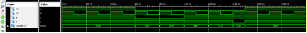
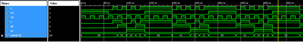
PRIMERA PARTE: Maquina de estado tipo MOORE
Analizar el código, hacer su simulación y dibujar las máquinas de estado del funcionamiento.
- ENTITY Diagrama_estados is
- PORT ( rst : in STD_LOGIC;
- CLK : in STD_LOGIC;
- a : out STD_LOGIC;
- b : out STD_LOGIC;
- state: out STD_lOGIC_VECTOR(3 downto 0)
- );
- end Diagrama_estados;
- architecture synth of Diagrama_estados is
- SIGNAL pstate : std_logic_vector(3 downto 0);
- SIGNAL n_state: std_logic_vector (3 downto 0);
- BEGIN
- --maquina de estados
- PROCESS (clk, rst)
- BEGIN
- IF rst = '1' then
- pstate <= "0000";
- ELSIF clk = '1' AND clk'event then
- pstate <= n_state;
- END IF;
- END PROCESS;
- state <= pstate;
- n_state <= "0001" when (pstate = "0000") ELSE
- "0010" when (pstate = "0001") ELSE
- "0011" when (pstate = "0010") ELSE
- "0100" when (pstate = "0011") ELSE
- "0101" when (pstate = "0100") ELSE
- "0011" when (pstate = "0101") ELSE
- "0111" when (pstate = "0011") ELSE
- "1000" when (pstate = "0111") ELSE
- "1001" when (pstate = "1000") ELSE
- "0000";
- a <='1' when pstate = "0000" else --0
- '0' when pstate="0001" ELSE -1
- '0' when pstate="0010" ELSE -2
- '1' when pstate="0011" ELSE -3
- '1' when pstate="0100" ELSE -4
- '1' when pstate="0101" ELSE -5
- '1' when pstate="0110" ELSE -6
- '1' when pstate="0111" ELSE -7
- '1' when pstate="1000" ELSE -8
- '1' when pstate="1001" ELSE -9
- '0';
- b <='1' when pstate = "0000" else --0
- '1' when pstate="0001" ELSE -1
- '1' when pstate="0010" ELSE -2
- '1' when pstate="0011" ELSE -3
- '1' when pstate="0100" ELSE -4
- '0' when pstate="0101" ELSE -5
- '0' when pstate="0110" ELSE -6
- '1' when pstate="0111" ELSE -7
- '1' when pstate="1000" ELSE -8
- '1' when pstate="1001" ELSE -9
- '0';
- END synth;
- LIBRARY ieee;
- USE ieee.std_logic_1164.ALL;
- ENTITY test_bench13 IS
- END test_bench13;
- ARCHITECTURE behavior OF test_bench13 IS
- COMPONENT implementacion13
- PORT(
- rst : IN std_logic;
- clk : IN std_logic;
- a : OUT std_logic;
- b : OUT std_logic;
- state: OUT std_logic_vector(3 downto 0)
- );
- END COMPONENT;
- --Inputs
- SIGNAL rst : std_logic := '0';
- SIGNAL clk : std_logic := '0';
- --Outputs
- SIGNAL a : std_logic;
- SIGNAL b : std_logic;
- SIGNAL state : std_logic_vector(3 downto 0);
- BEGIN
- -- Instantiate the Unit Under Test (UUT)
- utt : implementacio13 PORT MAP(
- rst => rst,
- clk => clk,
- a => a,
- b => b,
- state => state
- );
- stim_proc : process
- begin
- clk <= '1';
- rst <= '1';
- wait for 10 ns;
- clk <= '0';
- rst <= '1';
- wait for 10 ns;
- clk <= '1';
- wait for 10 ns
- clk <= '0';
- wait for 10 ns
- clk <= '1';
- wait for 10 ns
- clk <= '0';
- wait for 10 ns
- clk <= '1';
- rst <= '0';
- wait for 10 ns;
- clk <= '0';
- wait for 10 ns;
- clk <= '1';
- wait for 10 ns;
- clk <= '0';
- wait for 10 ns;
- clk <= '1';
- wait for 10 ns
- clk <= '0';
- wait for 10 ns;
- clk <= '1';
- wait for 10 ns
- clk <= '0';
- wait for 10 ns;
- clk <= '1';
- wait for 10 ns
- end process;
- END;
- library IEEE;
- use IEEE.STD_LOGIC_1164.ALL;
- entity implementation is
- Port (
- RST : in std_logic;
- up_down : in std_logic;
- clk : in std_logic;
- Q0,Q1 : oue std_logic
- state: out std_logic_vector (1 downto 0)
- );
- end implementation;
- architecture behavior of implementation is
- SIGNAL pstate: std_logic_vector (1 downto 0);
- SIGNAL n_state : std_logic_vector (1 downto 0);
- begin
- process (RST, clk)
- begin
- if RST ='1' then
- pstate <= "00";
- elsif clk = '1' and clk'event then
- pstate <= n_state;
- end if;
- end process;
- n_state<= "01" when (pstate="00" and upd_down='1') else
- "11" when (pstate="01" and up_down='1') else
- "10" when (pstate="11" and up_down='1') else
- "10" when (pstate="00" and up_down='0') else
- "11" when (pstate="10" and up_down='0') else
- "01" when (pstate="11" and up_down='0') else
- "00";
- Q0 <= '0' when pstate="00" else
- '1' when pstate="01" else
- '0' when pstate="10" else
- '1';
- Q1 <= '0' when pstate="00" else
- '0' when pstate="01" else
- '1' when pstate="10" else
- '1';
- end behavior;
- LIBRARY ieee;
- use ieee.std_logic_1164.ALL;
- ENTITY simula IS
- END simula;
- ARCHITECTURE behavior OF simula IS
- COMPONENT implementacion
- PORT(
- RST : IN std_logic;
- up_down : IN std_logic;
- clk : IN std_logic;
- Q0 : OUT std_logic;
- Q1 : OUT std_logic;
- state : OUT std_logic_vector (1 downto 0)
- );
- END COMPONENT;
- --Inputs
- SIGNAL RST : std_logic := '0';
- SIGNAL up_down : std-logic := '0';
- SIGNAL clk : std_logic := '0';
- --Outputs
- SIGNAL Q0 : std_logic;
- SIGNAL Q1 : std_logic;
- SIGNAl state : std_logic_vector (1 downto 0);
- BEGIN
- uut : implementacion PORT MAP(
- RST => RST,
- up_down => up_down,
- clk => clk,
- Q0 => Q0,
- Q1 => Q1,
- state => state
- );
- stim_proc : process
- begin
- clk <= '1';
- RST <= '1';
- up_down <= '0';
- wait for 10 ns;
- clk <= '0';
- RST <= '1';
- wait for 10 ns;
- clk <= '1';
- wait for 10 ns;
- clk <= '0';
- wait for 10 ns
- clk <= '1';
- wait for 10 ns
- clk <= '0';
- wait for 10 ns;
- clk <='1';
- RST <= '0';
- up_down<='0'
- wait for 10 ns;
- clk <= '0';
- up_down <= '0';
- wait for 10 ns;
- clk <= '1';
- up_down <= '0';
- wait for 10 ns;
- clk <= '0';
- up_down <= '0';
- wait for 10 ns;
- clk <= '1';
- up_down <= '1';
- wait for 10 ns;
- clk <= '0';
- up_down <= '1';
- wait for 10 ns;
- clk <= '1';
- up_down <= '1';
- wait for 10 ns
- clk <= '0';
- up_down <= '1';
- wait dor 10 ns;
- end process;
- END;
- S0 = 00
- S1 = 01
- S2 = 10
- S3 = 11
- library IEEE;
- use IEEE.std_logic_1164.ALL;
- entity imple is
- Port ( y : in std_logic;
- rst : in std_logic;
- clk : in std_logic;
- z : in std_logic;
- Q0: out std_logic;
- Q1 : out std_logic;
- state : out std_logic_vector(1 downto 0));
- end imple;
- architecture behavioral of imple is
- signal pstate : std_logic_vector (1 downto 0);
- signal n_state : std_logic_vector (1 downto 0);
- begin
- process (rst, clk)
- begin
- if RST ='1' then
- pstate <= "00";
- elsif clk ='1' and clk'event then
- pstate <= n_state;
- end if;
- end process;
- state <= pstate;
- n_state <= "01" when (pstate="00" and y='1' and z='1') else
- "10" when (pstate="01" and y='1' and z='0') else
- "11" when (pstate="10" and y='1' and z='1') else
- "00" when (pstate="11" and y='1' and z='1') else
- pstate;
- Q0 <= '0' when pstat ="00" else
- '1' when pstat ="01" else
- '0' when pstat ="10" else
- '1';
- Q1 <= '0' when pstat ="00" else
- '0' when pstat ="01" else
- '1' when pstat ="10" else
- '1';
- end behavioral;
- LIBRARY ieee;
- use ieee.std_logic_1164.ALL;
- ENTITY simula IS
- END simula;
- ARCHITECTURE behavior OF simula IS
- COMPONENT imple
- PORT(
- rst : IN std_logic;
- y : IN std_logic;
- clk : IN std_logic;
- z : in std_logc;
- Q0 : OUT std_logic;
- Q1 : OUT std_logic;
- state : OUT std_logic_vector (1 downto 0)
- );
- END COMPONENT;
- --Inputs
- SIGNAL y : std_logic := '0';
- SIGNAL rst : std-logic := '0';
- SIGNAL clk : std_logic := '0';
- SIGNAL z : std_logic := '0';
- --Outputs
- SIGNAL Q0 : std_logic;
- SIGNAL Q1 : std_logic;
- SIGNAl state : std_logic_vector (1 downto 0);
- BEGIN
- uut : imple PORT MAP(
- y => y,
- rst => rst,
- clk => clk,
- z => z,
- Q0 => Q0,
- Q1 => Q1,
- state => state
- );
- stim_proc : process
- begin
- clk <= '1';
- rst <= '1';
- wait for 10 ns;
- clk <= '0';
- rst <= '1';
- wait for 10 ns;
- clk <= '1';
- wait for 10 ns;
- clk <= '0';
- wait for 10 ns
- clk <= '1';
- wait for 10 ns
- clk <= '0';
- wait for 10 ns;
- clk <='1';
- rst <= '0';
- y <='0'
- z <='0';
- wait for 10 ns;
- clk <= '0';
- y <= '1';
- z <= '1';
- wait for 10 ns;
- clk <= '1';
- y <= '0';
- z <= '1';
- wait for 10 ns;
- clk <= '0';
- y <= '1';
- z <= '0';
- wait for 10 ns;
- clk <= '1';
- y <= '0';
- z <= '0';
- wait for 10 ns;
- clk <= '0';
- y <= '1';
- z <= '1';
- wait for 10 ns;
- clk <= '1';
- y <= '0';
- z <= '0';
- wait for 10 ns
- y <= '1';
- z <= '1';
- wait dor 10 ns;
- end process;
- END;
- library IEEE;
- use IEEE.STD_LOGIC_1164.ALL;
- use IEEE.STD_LOGIC_ARITH.ALL
- use IEEE.STD_LOGIC_UNSIGNED.ALL
- use IEEE.NUMERIC_STD.ALL
- entity imple is
- port ( clk: in STD_LOGIC;
- conteo: in STD_LOGIC;
- salida: out STD_LOGIC_vector(7downto 0)
- );
- end imple;
- architecture behavioral od imple is
- SIGNAL cuenta: STD_LOGIC_VECTOR (7 downt 0) :="00000000";
- begin
- process (clk)
- begin
- if clk ='1' and clk'event then
- if conteo ='1' then
- cuenta <= cuenta +1;
- else
- cuenta <= cuenta - 1;
- end if;
- end if;
- end process;
- salida <= cuenta;
- end behavioral;
- LIBRARY ieee;
- USE ieee.std_logic_1164.ALL;
- ENTITY imple_TB is
- END imple_TB;
- ARCHITECTURE behavior OF imple_TB IS
- --Component Declaration for the Unit Under Test (UUT)
- COMPONENT imple
- PORT(
- clk : IN std_logic;
- conteo: IN std_logic;
- salida : OUT std_logic_vector(7 downto 0)
- );
- END COMPONENT;
- --Inputs
- signal clk : std_logic := '0';
- signal conteo : std_logic := '0';
- -- Outputs
- signal salida : std_logic_vecto (7 downto 0);
- BEGIN
- -- Instatiate the Unit Under Test (UUT)
- utt: imple PORT MAP (
- clk => clk,
- conteo => conteo,
- salida => salida
- );
- --Stimulus process
- stim_proc: process
- begin
- clk <= '0',
- conteo <= '1';
- wait for 10 ns;
- clk <= '1',
- conteo <= '1';
- wait for 10 ns;
- clk <= '0',
- conteo <= '1';
- wait for 10 ns;
- clk <= '1',
- conteo <= '1';
- wait for 10 ns;
- clk <= '0',
- conteo <= '1';
- wait for 10 ns;
- clk <= '1',
- conteo <= '1';
- wait for 10 ns;
- clk <= '0',
- conteo <= '1';
- wait for 10 ns;
- clk <= '1',
- conteo <= '1';
- wait for 10 ns;
- clk <= '0',
- conteo <= '1';
- wait for 10 ns;
- clk <= '1',
- conteo <= '1';
- wait for 10 ns;
- clk <= '0',
- conteo <= '1';
- wait for 10 ns;
- clk <= '1',
- conteo <= '1';
- wait for 10 ns;
- clk <= '0',
- conteo <= '1';
- wait for 10 ns;
- clk <= '1',
- conteo <= '1';
- wait for 10 ns;
- clk <= '0',
- conteo <= '1';
- wait for 10 ns;
- clk <= '1',
- conteo <= '1';
- wait for 10 ns;
- wait;
- end process;
- END;
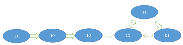
SEGUNDA PARTE: Maquina de estado tipo MOORE
Con el ejemplo anterior escribir y simular en VHDL el siguiente diagrama de estado.
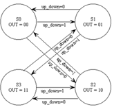

TERCERA PARTE: Maquina de estado tipo Mealy
Con el primer ejemplo, codificar, escribir y simular en VHDL el siguiente diagrama de estado
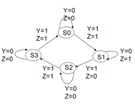
Le damos valores a las salidas ( codificamos)
Aplicación de lo aprendido
Realice el diseño de un contador ascendente/ descendente de 8 bits controlable mediante un bit para el cual en cero cuente descendentemente y en 1 ascendentemente. Usando contadores o máquina de estados.

Pueden descargar los archivos de ISE desde el siguiente enlace:https://github.com/mokuzaru/vhdl_labs